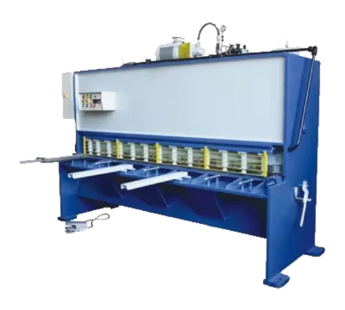
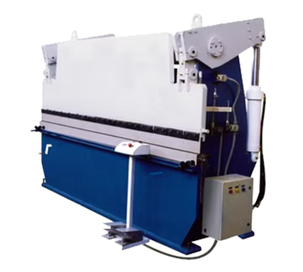
Accurate bends depend on more than pressing a sheet between a punch and V-die: force, tooling geometry, ram alignment, material variation and measurement all affect the finished angle and flange. By the end, you will be able to plan a bending operation, calculate whether the brake has enough capacity, correct common sources of error and specify the checks needed for repeatable production.
Key takeaways
- Define material, thickness, bend length, angle and measurement method before setup.
- Use the correct punch and die opening for the material and bend radius.
- Run a controlled first-off bend, then adjust angle and flange dimensions.
- Check hydraulic oil, tooling alignment, backgauges and calibration on a maintenance schedule.
What determines the accuracy of a hydraulic press brake bend?
Finished-part bend accuracy depends on the machine, tooling and material together, not on the CNC display resolution alone. Specify the working length, material grade and thickness, bend length, punch and die, target angle, flange dimensions, load condition, warm-up temperature and measurement method before judging performance.
A positioning resolution or repeatability figure without those conditions proves little.
| Variable | What it controls | What to verify |
|---|---|---|
| Y1 and Y2 axes | Ram parallelism at both ends | Equal tool height under the actual load |
| Hydraulic force and pressure stability | Deflection and consistent forming | Adequate tonnage, stable pressure and correct crowning |
| Punch, die and tool height | Bend radius, angle and flange position | Worn edges, matched tooling and clean seating |
| Back gauge and stroke control | Blank location and forming depth | Repeatable stops, aligned sheet and programmed bend data |
| Sheet thickness, strength and grain | Springback, cracking and final angle | Measured thickness, tensile grade and grain direction |
A synchronised hydraulic press brake uses Y1 and Y2 independently to keep the ram parallel and compensate for unequal loading. A single nominal Y-axis value does not confirm equal height at both ends.
Bed and ram deflection can make the centre angle differ from the side-frame angle, so mechanical or hydraulic crowning must match the bending load.
The back gauge establishes flange position; it does not set the finished angle. Check the bend line against the V-die, keep the sheet seated, and inspect both flange dimensions and angle. Bending parallel to the rolling direction also raises cracking risk in high-strength sheet, especially with a small inside radius.
How do you set up and run a normal bending cycle?
Clean the tooling stations before setup; a chip under a die shoulder changes the effective height and shifts the bend line. Seat the punch and V-block firmly, check that their lengths and openings match the job, and confirm the punch is centred over the die.
1. Fit the punch and V-block, then align their centres with the machine’s reference line. Check that the punch tip is undamaged, the die shoulders are level, and every tool segment is fully seated.
2. Program the back gauge for the required flange dimension, not for the finished angle. Bring the gauge fingers to the same height and confirm they are square to the bend axis; uneven fingers twist the sheet during positioning.
3. Place the sheet flat on the die, with its edge held against both gauge fingers. Apply steady contact without forcing the sheet sideways, and check sheet alignment across the full bend length.
4. Move the sheet until the marked bend line sits directly beneath the punch tip. Support long or heavy sheets so their weight does not pull the bend line away from the punch or lift them off the V-block.
5. Run the programmed stroke at the specified speed and pressure, keeping hands outside the guarded zone. Let the ram return fully before removing the part, then measure the first flange and angle; correct the setup only after identifying whether the error is position or forming geometry.
How do punch, die opening and forming method affect force and bend quality?
Punch selection starts with the required inside bend radius and material thickness. Use a punch-tip radius close to the target radius; a sharp tip concentrates force and can mark or crack high-strength sheet. Die opening controls the radius, load and sensitivity to thickness variation.
The 6–8 times thickness rule is only a starting point: narrow flanges, large radii and high-strength steel need a different V-opening.
| Method | Tooling and load | Bend-quality consequence |
|---|---|---|
| Air bending | The punch penetrates without flattening the sheet against the die. Estimate F(kN) ≈ 1.42 × tensile strength(N/mm²) × bend length(mm) × thickness²(mm²) ÷ V-opening(mm). | Lowest force and flexible angles, but more springback and greater sensitivity to material changes. |
| Bottoming | The sheet contacts the V-die faces. Use substantially more force than air bending and confirm the machine’s rated load. | Less springback, but inconsistent thickness or tooling can shift the final angle. |
| Coining | The punch drives deeply into the bend until the material yields locally. Allow the highest force and tooling stress. | Minimal springback, but excessive load can damage tooling or mark the part. |
Treat that equation as a press force calculation, not a guaranteed rating. Use tensile strength, not yield strength, or the result can understate the load. Check force across the full bend length, then compare it with the machine’s capacity and the tooling’s limit.
Clean seating matters: debris or an uneven die shoulder changes the effective geometry. Set the bend allowance with a K-factor validated for that method, radius and material.
How do you correct for material variation and verify the first-off part?
A first-off angle that is 1° open can produce an oversized assembly even when the back-gauge position is correct. Measure the formed part before releasing the batch, then adjust the CNC bend angle or punch depth for the measured springback.
Use springback compensation based on the actual sheet, not only the nominal bend allowance. Update the bend deduction or angle correction when thickness, yield strength, tensile strength, temper or mill batch changes. The K-factor affects the calculated bend allowance, but it does not remove springback; a measured trial bend still decides the correction.
Record these variables with the approved program:
- Material grade, thickness and batch or heat number
- Grain direction relative to the bend line
- Inside radius, V-die opening and punch nose radius
- Target angle, flange lengths and bend length
Bending parallel to the grain can increase cracking risk, particularly in high-strength sheet or at small inside radii. Change the bend orientation, increase the radius or qualify a separate program when the material specification changes.
Check the first-off part with an angle gauge and calibrated measuring tools. Verify the included angle, both flange dimensions, inside radius, bend location and critical hole-to-bend or edge-to-bend distances against the drawing. Record the measured values, tooling, program correction and batch number; approve production only after every specified tolerance passes.
A correct flange position does not prove a correct angle.
What should you specify when choosing and maintaining a hydraulic press brake?
Specify the machine against your actual part envelope, not a catalogue rating alone. Confirm the working length, rated tonnage, maximum material grade and thickness, longest bend length, tooling, target angle, flange dimensions, load condition, warm-up temperature and measurement method in the acceptance specification.
| Accuracy claim | What to verify | Why it matters |
|---|---|---|
| Repeatability | The ram and CNC back gauge return to the same positions under a defined test | A machine can repeat the wrong position |
| Absolute accuracy | Measured angle, flange size and ram position against calibrated references | Display resolution does not prove finished-part accuracy |
| Ram control | Independent Y1 and Y2 control, with parallelism checked under load | One nominal Y-axis value cannot confirm both ends are level |
- Size tonnage from the actual material and V-opening. A rough air-bending estimate is F(kN) ≈ 1.42 × tensile strength × bend length × thickness² ÷ V-opening; do not substitute yield strength or ignore bottoming and coining loads.
- Test the CNC back gauge, stroke control and angle measurement with a documented first-off procedure.
- Confirm fixed guards, emergency stops, foot-switch protection, overload control and safe access around the die.
- Ask for the hydraulic maintenance schedule: oil grade, filtration, leak inspection, hose and seal replacement, pressure checks and service records.
- Confirm who supplies calibration, spare valves and seals, operator training and response times. Valaba Machine Tools can help you compare a press brake against these production requirements rather than choosing by tonnage alone.
Clean tool seats and inspect punch tips and die shoulders; debris or wear changes the bend geometry. Use a written acceptance test before purchase, then repeat it after installation and major service.
Related product
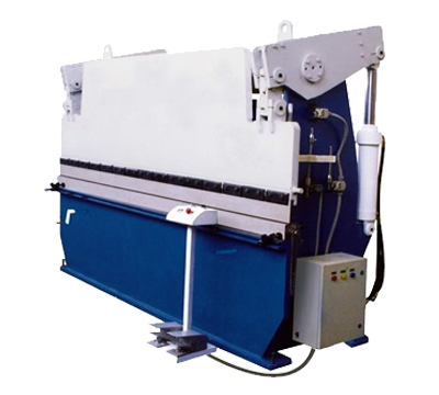 | POWER PRESS Steel Body Hydraulic Press Brake. Standard Accessories : Electric Motor, Control Panel with Selection of Inch – Once – Auto mode of operation, Foot... View product → |
Frequently asked questions
What determines hydraulic press brake bend accuracy?
Accuracy depends on machine rigidity, ram and backgauge alignment, tooling condition, material grade and thickness, bend length, springback and measurement method.
How do you run a normal hydraulic press brake bending cycle?
Warm up the machine, load the program, install and align the tooling, set the backgauge, position the sheet, make a slow first bend and inspect the part before production.
How do punch and die selection affect bend quality?
Punch radius and die opening control the inside radius, forming force, surface marks and springback. Choose tooling for the material, thickness and target bend.
How do you correct material variation and verify the first-off part?
Measure the first part's angle and flange dimensions, compare them with the drawing, adjust bend depth or compensation, then repeat the check before releasing the batch.
What should you specify when choosing and maintaining a hydraulic press brake?
Specify working length, maximum tonnage, stroke, daylight, throat depth, CNC axes, backgauge accuracy, tooling compatibility and required material range. Maintain alignment, hydraulics, lubrication and calibration.