A press selected by headline tonnage alone can produce inaccurate parts, damage a die, overload its frame or create an unsafe stopping distance. By the end, you will be able to calculate the real load, compare press types and dimensions, verify die and production-line compatibility, and write an acceptance specification for the machine you need.
Key takeaways
- Calculate peak load at the actual working position, not only nominal tonnage.
- Check frame stiffness, drive type, die envelope, and usable stroke.
- Specify safety controls, noise limits, floor loading, and non-production modes.
- Write an acceptance specification before requesting machine quotations.
Calculate the Real Forming Load Before Comparing Tonnage
A 100-ton press does not necessarily deliver 100 tons where your operation needs it. Determine the peak load at the actual working position, then compare it with usable forming force, die capacity and the machine’s load limits.
1. Calculate forming, piercing, bending, stripping and acceleration loads separately. For blanking or piercing, use material shear strength × cut perimeter × thickness; for bending or drawing, use the die maker’s forming equation for the material, radius and geometry.
Add the loads that occur simultaneously, then include a safety margin for variation in thickness, strength and lubrication.
2. Compare the result with nominal tonnage and the force-position curve. A mechanical press is rated at a specified rated point above bottom dead centre (BDC), not throughout its stroke. Request the supplier’s curve and confirm that the press supplies the required usable forming force at your forming position.
3. Check eccentric loading separately. Compare the load centre and resulting moment with the maker’s permitted limits; excessive offset causes slide tilting, guide wear and bearing damage even when tonnage appears sufficient.
4. For a hydraulic press, compare force, forming speed, decompression and return speed at each cycle stage. For coil-fed work, verify feeder and straightener capacity too, because line limits can restrict production before press tonnage does.
Choose the Frame and Drive for the Workpiece and Process
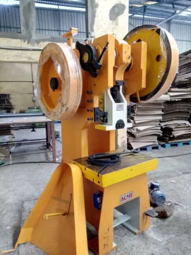
A C-frame power press gives three-sided access, making it practical for punching, blanking and short, easy-to-handle parts. Its open throat also deflects more under off-centre loading, which can reduce die alignment and tool life. Use an H-frame press for hydraulic forming, deeper workpieces and loads that benefit from column support.
| Frame | Main advantage | Choose it when |
|---|---|---|
| C-frame power press | Open access and compact layout | The die is modest in width and loading stays close to centre |
| H-frame press | Column support and full-stroke hydraulic force | Deep forming, heavy workpieces or controlled force and speed matter |
| Straight-side press | Highest rigidity and resistance to deflection | Progressive dies, wide tooling or off-centre production loads demand alignment |
The fixed frame versus inclinable frame decision affects both stability and handling. Choose a fixed frame for repeated production and accurate die alignment; choose an inclinable frame when gravity-assisted part discharge and faster access outweigh reduced rigidity.
Mechanical drives suit high-speed, repeatable stamping, but verify the force-versus-position curve and rated point because peak tonnage applies near bottom dead centre. Hydraulic drives provide force through much of the stroke, while approach, forming, decompression and return speeds limit output.
Servo drives add programmable stroke motion, speed and dwell for demanding forming profiles, but compare stopping data, duty cycle and demonstrated production rate rather than maximum strokes per minute.
Match Press Dimensions to the Die Envelope
A die that fits the bolster can still fail to run if its shut height, slide opening or mounting pattern exceeds the press envelope. Check the complete interface before ordering, not just bolster length and width.
| Press dimension | Why it matters | What to verify |
|---|---|---|
| Shut height and daylight | Determines whether the closed die fits and whether the open press provides tool clearance | Minimum and maximum shut height, slide adjustment, total daylight and stroke length |
| Bolster and slide | Controls support, alignment and tool access | Bolster and slide length, width, openings, thickness, T-slots and mounting-hole pattern |
| Capacity and travel | Prevents overload and premature die damage | Die weight, die-height adjustment, cushion or knockout capacity, and strokes per minute |
Confirm the die remains serviceable at its installed position: leave room for punch replacement, slug removal, lubrication, sensors and safe access to clamps. A narrow opening can make routine maintenance impossible even when the die technically fits.
Request slide-parallelism readings at several positions, shut-height repeatability and stopping-time data at the intended speed. Maximum strokes per minute does not prove safe stopping; check clutch and brake duty-cycle limits, brake monitoring and permitted stops per minute. For coil-fed dies, match feed height, pitch, stock width and transfer clearance to the press.
Match the Machine to the Operation and Production Line
Choose the press from the process, not from the material name alone. Blanking, punching and piercing create short, high-impact loads; confirm that the press and die tolerate shock, stripping force and off-centre loading.
| Operation | Selection effect | Production-line implication |
|---|---|---|
| Blanking | Prioritise rigid guidance, suitable energy and reliable slug handling. | Add scrap evacuation and blank stacking. |
| Punching | Check repeated peak loads, punch alignment and stripping capacity. | Match stroke rate to part transfer and scrap removal. |
| Piercing | Allow for slug disposal, reverse loads and narrow punch support. | Prevent blocked chutes from stopping the line. |
| Bending | Select controllable stroke and adequate overrun protection for angle consistency. | Coordinate backgauges, transfers or manual loading. |
| Coining | Use high bottom-of-stroke force and a rigid die-support system. | Expect slower cycles and greater tool wear. |
| Embossing | Match stroke control and force distribution to the pattern depth. | Verify feeding and part orientation after forming. |
| Drawing | Provide sufficient stroke, blank-holder control and smooth force application. | Coordinate lubrication, transfer timing and wrinkle control. |
| Progressive-die work | Match press speed, feed accuracy, die pitch and shut height to the strip layout. | Rate the complete line by its slowest element: press, feeder, uncoiler, straightener, lubrication or part removal. |
Request a demonstrated cycle with your die and material. Include forming, piercing, bending, stripping and acceleration loads, then review die capacity, floor loads and overhung feed equipment together; an unloaded press speed proves little.
Check Safety, Noise, Floor Loading and Non-Production Modes
Treat safeguarding, installation and non-production operation as acceptance conditions, not items to resolve after delivery. A press with inadequate stopping performance, floor capacity or setup access can make an otherwise suitable die unusable.
1. Specify the point-of-operation safeguarding: fixed barriers, interlocked guards, a presence-sensing device or two-hand control. Require access, muting, reset and fault-response details for each option.
2. Obtain the measured total stopping time, including clutch and brake response, control response and ram stopping travel. Verify the presence-sensing device’s minimum mounting distance using the applicable jurisdictional formula; a generic light curtain cannot compensate for excessive stopping distance.
3. Request total machine weight, point and distributed floor loads, anchoring requirements, foundation drawings, allowable floor deflection and vibration-isolation requirements. Include dynamic die loads and overhung feeder or conveyor equipment in the review.
4. Require documented modes for die setting, troubleshooting, jam clearing and maintenance. Check for restricted-speed or inch controls, safe die-space access and lockout/tagout provisions; guarding that works only during production is incomplete.
5. Measure noise with the intended die, material and production cycle. In U.S. plants, plan hearing conservation at an 8-hour time-weighted average of 85 dBA and treat 90 dBA as the 8-hour permissible exposure limit under OSHA’s occupational-noise rule.
For U.S. installations, check OSHA requirements for mechanical presses, including controls, brake monitoring, inspections and maintenance. Evaluate the guarding and consensus standards that apply to the actual press type, because hydraulic presses are not automatically covered by every mechanical-press provision.
Write an Acceptance Specification Before Requesting Quotations
Require a witnessed acceptance test using your actual material thickness range, representative die, lubrication and target production rate. An unloaded stroke demonstration proves almost nothing.
1. Record force or hydraulic pressure over repeated cycles, then verify force repeatability at the forming point. Measure slide parallelism at the top, middle and bottom of the stroke, and shut-height repeatability after repeated adjustments.
2. Run the feeder, straightener, lubrication system and die together. Document feeder synchronization, demonstrated strokes per minute, strip position and part-transfer reliability; the slowest line component sets the usable rate.
3. Inspect sample parts against your drawing. Require measurements for critical dimensions, hole location, bend angle, draw depth and burr limits, with a stated sample size and pass/fail limits.
4. Test stopping performance in normal, inch, setup and emergency-stop modes. Require guarding, die-access and lockout/tagout documentation for jam clearing and maintenance.
5. Measure noise with the intended die, material and cycle, plus accessible-surface temperature and oil leakage. Record sound levels at operator positions; 85 dBA over an eight-hour time-weighted average triggers OSHA hearing-conservation planning.
Valaba Machine Tools can use this specification to compare a quoted press against demonstrated results rather than nominal tonnage alone. Put every acceptance value, test instrument and remedy for failure into the purchase order.
Related products
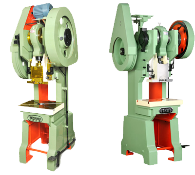 | POWER PRESS Steel Body Power Press Fixed & Inclinable. Frame : The frame is of all steel construction, fabricated from steel plates with suitable cross ribbings. View product → |
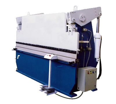 | POWER PRESS Steel Body Hydraulic Press Brake. Standard Accessories : Electric Motor, Control Panel with Selection of Inch – Once – Auto mode of operation, Foot... View product → |
Frequently asked questions
How do you calculate the real forming load before comparing press tonnage?
Calculate peak load at the actual working position, then compare it with usable forming force, die capacity, and machine load limits.
How should you choose the press frame and drive?
Match the frame and drive to the workpiece, forming process, required stiffness, stroke, speed, and production duty.
Why must press dimensions be matched to the die envelope?
Check that the bolster, shut height, stroke, daylight, throat depth, and die space accommodate the complete die set.
What safety and site factors should you check before selecting a press?
Check guarding, two-hand controls or presence sensing, emergency stops, noise, floor loading, and non-production operating modes.
What should an acceptance specification include?
State forming-load calculations, dimensional requirements, operating conditions, safety features, noise and floor limits, testing, and acceptance criteria.