Choose hydraulic bending when the busbar’s material, cross-section and production volume make manual forming too slow, tiring or inconsistent. The decision depends on more than cylinder force: you must match the machine’s capacity envelope, tooling, bend radius, repeatability and process controls to the actual electrical fabrication work.
Key takeaways
- Use hydraulic bending when busbar volume, thickness, or repeatability exceeds manual capacity.
- Match force and tooling to copper or aluminium, cross-section, bend direction, and inside radius.
- Compare hydraulic benders with press brakes by setup time, bend control, and conductor protection.
- Validate bend angle, radius, surface condition, and hole alignment before assembly.
Does your busbar and workload justify hydraulic bending?
A hydraulic busbar bending machine suits your work only if it matches the conductor, bend orientation and production demand. Confirm that the model is designed for copper busbar and aluminium busbar, not merely sheet steel; the required force changes with alloy, temper, cross-section, inside radius, tooling and flatwise or edgewise forming.
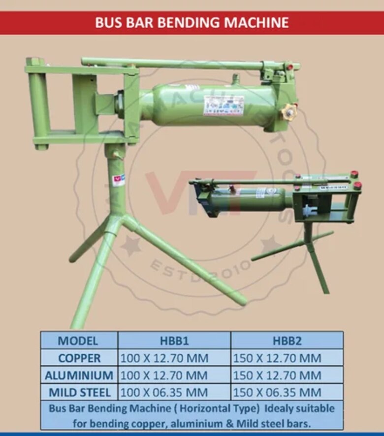
Read capacity as a width-by-thickness envelope. In the busbar dimensions 150 × 12 mm example, 150 mm is the maximum width and 12 mm the maximum thickness, subject to the stated material, bend radius and orientation. Check maximum cross-sectional area and the largest permitted bend radius beside the headline capacity.
Tonnage alone does not prove that the machine can form your bar without flattening or cracking.
Use this buying checklist:
- Choose hydraulic actuation for thick or wide bars, repeated 30°, 45° and 90° bends, or schedules with many identical parts; high force reduces operator effort and angle variation.
- Question the purchase for thin, narrow bars and occasional one-off bends, where setup, alignment and tooling-change time can exceed the benefit of hydraulic power.
- Include insulated, laminated and coated bars. A machine intended for bare copper can damage their surface unless it has suitable tooling, pressure limits and a defined minimum radius.
- Require a witnessed trial with your actual alloy, temper, dimensions, finish and orientation; inspect final angle, radius, cross-section, tool marks, hole position and repeatability across several parts.
How does the machine form a controlled busbar bend?
Controlled hydraulic busbar bender operation starts with positioning, not pressure. Place the copper or aluminium bar against the angle stop, support or clamp it, and align the marked bend line beneath the forming die. The former provides bend radius control; the stop fixes location and the angle setting supports repeatability.
1. For a flatwise bend, use a broad former and die that support the bar across its wide face. This spreads force and limits crushing, deep tool marks and local thinning.
2. For an edgewise bend, fit tooling that supports the narrow edge and provides the specified inside radius. An unsuitable former can twist the bar or initiate cracking even when the cylinder has enough force.
3. For an offset bend, use a stepped or offset former matched to the required displacement. Keep both legs supported so the bar does not slip or deform outside the bend zone.
4. Start the hydraulic ram and let the forming die drive the bar around the former. Stop at the set angle or validated overbend, then retract the ram and remove the formed conductor.
5. Check the machine’s maximum bending angle and confirm repeatable 30°, 45°, 90° and custom-angle settings. A nominal 90° ram position does not guarantee a finished 90° bend.
Aluminium and harder copper tempers spring back after pressure is released. Validate the required overbend or angle-stop setting with sample bars, then inspect the final angle and radius; do not rely on pressure alone to correct poor tooling.
When is hydraulic power better than a press brake or manual bender?
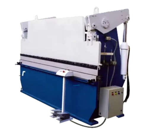
Hydraulic power is better when thick or wide copper or aluminium bars, repeated bends and production volume make manual force excessive. Compare a dedicated hydraulic busbar bender versus press brake tooling by geometry, effort, flexibility and repeatability—not cylinder capacity alone.
| Option | Tooling geometry | Operator effort and repeatability | Best fit |
|---|---|---|---|
| Manual busbar bender | Purpose-built former, with limited adjustment | Highest physical effort; consistent angles depend on the operator | Thin bars, prototypes and low quantities |
| Electric-hydraulic busbar tool | Busbar former with portable powered actuation | Moderate effort and repeatable angles after setup | Portable or moderate-volume work |
| General press brake | Punch and V-die may mark surfaces, misalign narrow bars, flatten the section or impose the wrong radius | High force capability, but electrical-busbar accuracy depends on improvised support and tooling | Parts that genuinely match the brake’s geometry |
| Hydraulic busbar bender | Interchangeable former and controlled radius support narrow conductors | Low operator input; stops and angle controls reduce variation | Thick or wide bars and repeated production bends |
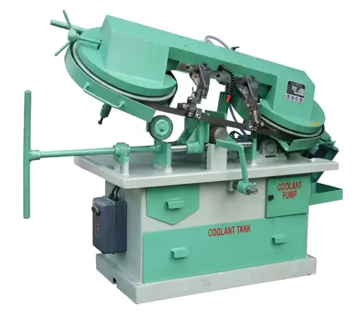
Compare the complete process: tooling changes, alignment time, fatigue, angle variation and inspection labour determine the cost per acceptable bend. A three-station busbar machine can cut handling when its standard cut, punch and bend stations match recurring parts; separate equipment offers more flexibility and dimensional control when sizes and operations change frequently.
A hydraulic machine is the wrong investment for one-off narrow bars if setup and changeover take longer than manual forming.
What fabrication controls protect the conductor and the finished assembly?
A busbar can look correctly bent yet fail through local heating, weak mounting or insulation damage. Inspect the busbar cross-section after bending for necking, flattening, cracks, burrs and deep tool marks; deburr cut edges and repair damaged plating or insulation under the assembly specification.
1. Establish the bend development before production. Calculate hole positions from the actual bend allowance or a validated sample, because bending changes finished length and hole location. Set a minimum busbar hole-to-bend distance on the fabrication drawing; a hole too close to the bend can distort, lose edge distance or crack the surrounding material.
2. Choose the punching sequence from the drawing and tooling. Punch before bending when the tooling supports the hole pattern without distortion; punch after bending when the formed geometry is needed to locate the holes accurately.
3. Define controls for insulated, laminated or coated busbar. Record the allowable surface pressure, minimum radius and coating damage limits, then inspect for exposed conductor, lifted plating and impressions that exceed those limits.
4. Inspect the completed assembly, not only the formed bar. Verify IEC 61439 clearances and creepage, support spacing, connection alignment and the temperature-rise design. IEC 61439 evaluates these characteristics at the switchgear or controlgear assembly level; a correct busbar cross-section after bending does not establish compliance.
How should you specify and validate a hydraulic busbar bender?
Specify the part, not the cylinder’s maximum tonnage. A useful busbar bender machine specification states the copper or aluminium alloy and temper, bare or insulated surface, width, thickness, cross-sectional area, flatwise or edgewise orientation, minimum inside radius, maximum angle, custom-angle range and required repeatability.
1. Ask which interchangeable dies support flat, edgewise and offset bends. Record allowable surface marking, burrs and cross-section deformation, including flattening or necking. A 150 × 12 mm capacity still depends on alloy, orientation, radius and tooling.
2. Require a witnessed machine trial with your actual busbar, including its surface finish and insulation or coating. Inspect final angle, inside radius, cross-section, tool marks and hole position, then check repeatability of busbar bends across several parts rather than accepting one successful ram stroke.
3. Assess hydraulic maintenance and safety alongside forming performance. Confirm the specified hydraulic oil, hose and fitting inspection points, pressure-relief protection, cylinder-seal life, guarding and prevention of unintended ram movement. Ask for replacement seals, compatible tooling and practical service access.
Use one acceptance sheet for every supplier, including Valaba Machine Tools, so equipment comparisons reflect your electrical fabrication requirements rather than brochure capacity. Reject the machine if it cannot meet the trial’s angle, radius, surface and repeatability limits with the production bar.
Frequently asked questions
When does a busbar workload justify hydraulic bending?
Hydraulic bending becomes worthwhile when you need repeatable angles, thicker or wider busbars, multiple bends, or production output beyond practical manual bending capacity.
How does a hydraulic busbar bending machine control the bend?
A hydraulic cylinder applies controlled force through a matched punch and die, while the tooling supports the busbar and sets the bend direction and radius.
When is hydraulic power better than a press brake or manual bender?
Choose hydraulic busbar tooling when electrical fabrication requires dedicated conductor support, fast setup for common bends, and protection against marking or flattening. Use a press brake for broader sheet-metal work and a manual bender for low-volume, lighter sections.
What controls protect the busbar during fabrication?
Use the specified inside radius, clean and aligned tooling, correct supports, controlled force, and bend inspection. Check for cracks, deep tool marks, twisting, thinning, and damaged insulation or plating.
How do you specify and validate a hydraulic busbar bender?
Specify copper and aluminium compatibility, maximum width and thickness, flatwise or edgewise capacity, minimum bend radius, force, tooling, angle control, and documentation. Validate it with sample bends measured for angle, radius, surface condition, and hole alignment.