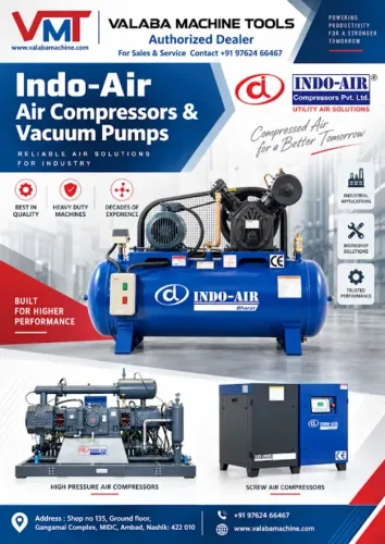
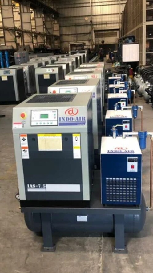
Production air demand rarely stays at the compressor’s nameplate rating: CNC machines, pneumatic tools, actuators and spray systems create changing loads, pressure losses and short peaks. By the end, you will be able to map that demand, select capacity and controls, specify air treatment, and check whether the installation can sustain the required pressure without wasting power.
Key takeaways
- Measure flow demand and pressure before selecting compressor capacity.
- Use variable-speed control when plant demand changes substantially.
- Specify filters and dryers from the required air-quality class.
- Keep the compressor room cool, clean and properly ventilated.
How twin screw rotors create a steady air stream
A rotary screw air compressor produces flow by drawing air through the air inlet into two parallel, counter-rotating grooves. The twin intermeshing rotors trap pockets of air, carry them along the casing, and reduce their volume as the grooves mesh.
This creates a smooth stream rather than the separate pressure pulses produced by a reciprocating compressor.
In oil-injected compression, oil enters the compression chamber to seal clearances, remove heat and lubricate the rotors. The oil-laden air then passes through:
- An air-oil separator that returns most oil to the circuit
- An oil cooler and air aftercooler that control operating temperature
- A discharge line carrying compressed air to the receiver and treatment equipment
Separator performance, oil filtration, oil cooling and condensate removal determine whether the system stays reliable. Downstream coalescing filtration still matters because a small amount of oil can pass the separator and contaminate air lines or the process.
The rotors can keep turning while production consumes air, so the compressor avoids the repeated starts and pressure surges associated with short-cycle piston operation. That suits CNC machines, actuators and pneumatic tools that need stable pressure across a shift.
Continuous duty does not mean continuous full-capacity output: a fixed-speed machine unloads when demand falls, and unloaded running still consumes power. Controls, cooling and maintenance therefore decide whether steady air delivery becomes efficient production or expensive idle time.
Size the compressor from measured demand, not motor horsepower
A motor rating cannot tell you how much usable air reaches the machines. Specify compressor capacity as free-air delivery (FAD) at the required discharge pressure in bar(g), with inlet temperature and pressure stated; use performance data tested to ISO 1217 rather than swept volume or nominal horsepower.
Measure the shift before selecting the machine. Log pressure and flow at short intervals across a representative production run, including:
- Base demand during normal machining
- Simultaneous tool, actuator, spray and CNC demand
- Shift changes and machine start-ups
- Measured leakage during idle periods
- Intermittent equipment and its run time
Compare the resulting profile with the compressor’s FAD and duty cycle. Size capacity for the sustained demand, not merely the highest instantaneous reading. If demand repeatedly exceeds FAD, pressure will decay until production equipment faults; if a fixed-speed compressor is too large, it will spend more time unloaded, still consuming power without producing air.
Size the receiver for the deficit during each short peak. A practical calculation is receiver volume = (peak FAD minus compressor FAD) × peak duration × atmospheric absolute pressure ÷ allowable receiver pressure swing. Use absolute pressures in the calculation, not bar(g) values alone.
For example, a 20 m³/min deficit lasting 30 seconds needs storage for 10 m³ of free air; the permitted pressure swing determines the vessel size. A wet receiver before the dryer removes bulk condensate, while a dry receiver after treatment buffers clean air. Neither receiver compensates for sustained demand above compressor FAD.
Match control strategy to changing plant demand
The wrong control strategy turns a steady production load into pressure swings, unnecessary cycling and wasted power. Match control behaviour to the demand profile rather than choosing the highest motor rating.
| Control | Pressure behaviour | Cycling and energy effect | Best fit |
|---|---|---|---|
| Load/unload control | Holds pressure between load and unload setpoints | An unloaded fixed-speed machine can still consume 15–30% of full-load input | Stable demand near the compressor’s rated flow |
| Modulation | Restricts inlet flow to follow demand | Reduces abrupt cycling but wastes power through throttling at low demand | Moderate, gradually changing demand |
| Variable-speed drive | Changes rotor speed to track demand | Cuts low-demand power use, but efficiency falls below its minimum stable speed | Wide demand variation |
A variable-speed drive is not unlimited turndown. If demand drops below its stable speed, the compressor can unload or stop; an oversized VSD unit can still run inefficiently.
With multiple machines, designate one trim compressor to absorb changing demand and keep the others near efficient loaded points. Poorly coordinated local controls make compressors fight over pressure, widening the pressure band and increasing load/unload cycles.
Use a receiver to damp short peaks and reduce rapid cycling, but do not treat it as extra capacity. A sustained demand above compressor free-air delivery will still reduce pressure. Set pressure at the point of use, then correct blocked filters, undersized dryers or restrictive piping instead of raising discharge pressure and increasing power consumption.
Build the air-treatment train around the required air quality
Specify air quality at the point of use under ISO 8573-1, with separate classes for particles, water and oil. “Clean” or “dry” is not a usable specification. An oil-injected compressor needs a separator, oil cooler, condensate management and coalescing filtration; an oil-free compressor still needs protection from intake, piping and seal contamination.
| Requirement | Dryer and filtration | Receiver and drain arrangement |
|---|---|---|
| General plant air | Refrigerated dryer, water separator and particulate filter | Wet receiver with automatic zero-loss drain; dry receiver after the dryer |
| Low-dew-point instrument air | Desiccant dryer, prefilter and afterfilter | Wet receiver before the dryer; dry receiver after it, with monitored drains |
| Paint, laser or product-contact air | Coalescing filter, refrigerated or desiccant dryer, and activated-carbon filter when oil vapour limits require it | Use dry, corrosion-resistant downstream storage and treat every condensate outlet |
Build the train in this order:
- Aftercooler and water separator to remove heat and bulk liquid.
- Wet receiver to cool incoming air and collect condensate.
- Automatic drains at the separator, receiver and filter bowls; route oily condensate to an approved treatment system.
- Coalescing prefilter before the dryer, then a particulate afterfilter. Add activated carbon only when the specified oil-vapour class demands it.
- Dry receiver after treatment to buffer short demand surges without raising compressor pressure.
A refrigerated dryer typically delivers about +3 °C pressure dew point. Choose a desiccant dryer for targets such as −40 °C or −70 °C, and price its purge-air or blower energy before selecting the class.
Protect output with the right compressor-room conditions
Keep the compressor room cooler than the machine’s maximum rated ambient temperature, and provide compressor room ventilation that removes hot discharge air without recirculating it to the intake. Leave the manufacturer’s service clearance around coolers, filters and separators; blocked airflow turns a clean machine into an overheating machine.
Specify capacity as free air delivery at the required discharge pressure and inlet conditions, not by motor horsepower. Confirm the selected model’s continuous-duty rating, control response and unloaded power, because a fixed-speed compressor still consumes energy while unloaded.
Monitor discharge temperature at every shift. A rising reading points to a dirty cooler, excessive room temperature, incorrect oil level or type, or restricted oil flow; continued operation can degrade lubricant, overload the separator and trigger a shutdown.
Treat oil management as a reliability system, not a refill task. Check oil level, filter condition, separator differential pressure, cooler cleanliness and condensate drains at the intervals in the service schedule. An oil-free machine still needs clean intake air and contamination control through piping, seals, dryers and filters.
Use heat recovery only after confirming a simultaneous heat load and the required temperature. Oil-cooling or cooling-water circuits can support space or process heating, but recoverable heat falls when the compressor unloads. Valaba Machine Tools can help compare compressor and dryer selections against these operating checks, rather than matching equipment to horsepower alone.
Related products
 | Air Compressors Valaba Machine Tools offers reliable and efficient screw air compressors designed to provide a continuous supply of compressed air for industrial,... View product → |
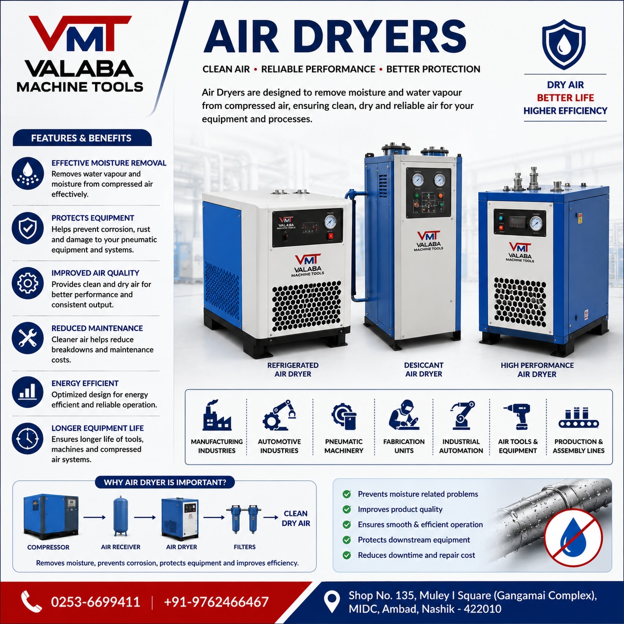 | Air Dryers are essential components of compressed air systems, designed to remove moisture and water vapour from compressed air before it reaches... View product → |
Frequently asked questions
How do twin screw rotors create a steady air stream?
Two counter-rotating intermeshing rotors trap air, carry it through the casing and reduce its volume continuously, producing a steady compressed-air flow.
How should you size a rotary screw air compressor?
Measure actual flow demand, operating pressure, leakage and future load before selecting capacity; motor horsepower alone does not show delivered air volume.
Which control strategy suits changing plant demand?
Use fixed-speed load-unload control for relatively stable demand and variable-speed control when demand changes frequently or across a wide range.
What air-treatment equipment does a compressor need?
Choose aftercoolers, separators, filters and dryers according to the required pressure dew point, oil content, particles and moisture at the points of use.
What compressor-room conditions protect output?
Provide clean intake air, adequate ventilation, drainage and service access while keeping room temperature within the compressor manufacturer's specified range.