
Start with the largest workpiece, the longest unsupported length, the stock diameter, and the jobs you run most frequently—not the lathe’s headline swing or motor rating. By the end, you will be able to turn those requirements into checks for capacity, workholding, tooling, control, site readiness, and production suitability.
Key takeaways
- Measure chuck jaws, fixtures and tool clearance—not just the finished part.
- Match spindle bore, chuck size, tooling and tailstock capacity as one system.
- Choose CNC, manual or automatic control from your actual work mix.
- Specify torque, speed, coolant, threading and acceptance tests before purchase.
Calculate the real turning envelope before comparing machines
Measure the largest rotating envelope in its actual setup, not the finished part alone. Record diameter, length, chuck or faceplate projection, tailstock contact, steady-rest position, tool overhang and chip-clearance space. Include the chuck jaws and fixture: they can exceed the workpiece diameter.
1. Calculate required swing over bed as the largest diameter that must rotate above the bed, plus twice your radial clearance. Calculate swing over cross-slide the same way at the tool-contact zone; this figure usually sets the practical maximum diameter.
2. Calculate required distance between centres from the spindle-nose datum to the tailstock-centre position, including chuck projection, part length, centre-drill depth and tailstock engagement. For chuck work, add the exposed part length and clearance behind the tool; do not use finished length alone.
3. Select bed length after allowing carriage travel, tailstock movement, steady-rest access and toolholder overhang. A long bed does not guarantee useful reach if the carriage cannot approach the shoulder. Check centre height against the chuck, jaws, cross-slide and maximum diameter, then confirm the stated lathe length leaves room for loading and chip removal.
4. Specify tailstock capacity separately: quill travel, quill diameter, Morse taper, support force and alignment. Require enough quill extension to support the actual part without placing the quill at its flexible limit or obstructing the tool.
Add the resulting clearances to the purchase specification, then prove them with the longest and largest workpiece in an acceptance trial. Include slenderness, unsupported bar and toolholder stick-out; chatter can limit production before motor power does.
Choose spindle, workholding and tooling capacity as one system
A spindle rated at 3,000 rpm does not make every chuck safe at 3,000 rpm. Confirm the chuck’s marked speed limit at the actual jaw mass, workpiece diameter, balance condition and lubrication state; centrifugal force reduces gripping force as speed rises.
Spindle bore also sets bar-work throughput. Measure the usable bore after fitting the spindle liner, guide bush, bar remnant allowance and bar-feeder interface. A nominal 52 mm bore may not pass 50 mm stock reliably once clearance and liner thickness are included.
Check that the spindle-nose capacity matches the required chuck register, thread or camlock pattern, drawtube and adapter.
| Component | Confirm before purchase | Failure if ignored |
|---|---|---|
| Three-jaw self-centring chuck | Jaw range, through-hole, gripping force, balance and rated rpm | Large or badly balanced work can slip or exceed the chuck’s safe speed |
| Four-jaw independent chuck | Plate diameter, jaw travel, backplate fit and clearance at full offset | The part may foul the bed, guards or toolholder during adjustment |
| Collet system | Collet standard, gripping range, length capacity and bar alignment | Existing collets may not fit, or short gripping may cause runout |
| Faceplate | Mounting pattern, slots, rated load and counterweight clearance | Irregular work can shift or overload the spindle |
| Tailstock | Quill travel and diameter, Morse taper, support force, alignment and tool clearance | Long work deflects, while a drill or centre cannot reach the cut |
| Tooling | Toolholder size, boring-bar diameter, insert geometry and overhang | Chatter appears before the motor reaches its rated power |
Use an acceptance trial with your longest overhang, slimmest part and existing holders. Record runout, chatter, support clearance and actual chuck speed limits; then verify that the drawtube, tailstock and tooling leave room for chip control and the intended boring depth.
Match the lathe type and control to your work mix
An engine lathe suits repair work and one-off parts because you can set up quickly, use existing tooling, and adjust feeds or dimensions at the machine. A geared-head lathe is a strong manual choice when you need dependable torque across varied materials without paying for CNC features you will rarely use.
| Work mix | Best fit | Why it fits |
|---|---|---|
| Repair work | Engine lathe | Fast manual adjustments and flexible workholding suit unknown or damaged parts. |
| One-off parts | Geared-head lathe | Low programming overhead keeps setup time and handling effort under control. |
| Repeat batches | Turret lathe | Multiple tools stay ready, reducing tool changes between identical operations. |
| Repeat batches with complex operations | CNC turning centre | Programs, offsets, probing and documented cycles improve repeatability. |
| Unattended production | CNC turning centre with bar feeder | Automatic tool changes, parts catching and bar feeding reduce operator intervention. |
Compare annual setup hours, handling time and batch frequency rather than purchase price alone. A CNC turning centre earns its cost when repeated setups, inspection, tool offsets or multiple operations consume operator time.
For bar-fed work, check the complete automation path before choosing the machine. Confirm spindle-bore alignment, usable bar-feeder range, remnant length, liner design, drawtube length, parts-catcher access, chip-conveyor behaviour and the control’s bar-change and tool-life sequences. A nominal 52 mm bore does not guarantee reliable 50 mm stock production once liner clearance and remnants are included.
Match torque, speed, feeds and coolant to the material
Use the spindle torque curve, not motor power alone, to judge roughing capacity. A low-speed heavy cut needs sustained spindle torque; a small-diameter finishing cut needs motor power, high rpm, balance and thermal stability. Ask for the torque and power curves, plus their duration rating.
| Material and cut | What to compare | Suitable machine features |
|---|---|---|
| Carbon steel roughing | High spindle torque at low rpm, low to medium feed, and stable power through the cut | Geared-head gearbox, rigid construction and flood coolant |
| Aluminium finishing | Wide spindle-speed range, high maximum rpm, fine feed and adequate power at speed | Variable-speed drive, balanced workholding and coolant that prevents chip welding |
| Stainless steel or alloy-steel cutting | Torque under low-speed load, low-vibration feed control and continuous chip evacuation | Gearbox or variable-speed drive with stable low-speed control, flood coolant and sufficient pump flow |
Compare the feed range with your actual work: coarse feeds remove stock quickly, while fine feeds control surface finish. Check threading feeds and pitch capability separately; a broad turning-feed range does not prove the lathe can cut your required thread.
A variable-speed drive gives rapid speed changes and useful control across diameters, but it does not replace low-speed torque. A gearbox supplies mechanical torque efficiently, while the drive handles speed adjustment.
Treat maximum rpm as a workholding limit, not just a spindle limit. Confirm the chuck’s rated speed, jaw condition, balance and gripping force at the diameter you will run.
Finally, test the intended cut with your tool overhang and workpiece support. Chatter, coolant temperature and spindle heat can limit output before the motor reaches rated power.
Verify threads, installation, automation and acceptance tests
A thread chart is not enough: confirm the machine’s actual pitch range, threading direction, and changeover method. A metric lead screw and an imperial lead screw produce different compatibility questions, while a quick-change gearbox may cover common pitches without supporting every pitch your drawings require.
Cut a sample thread in the materials and diameters you use, then check pitch with a gauge and major diameter with a micrometer.
Before delivery, make the installation drawing pass a physical inspection. Check floor loading and anchor positions, door and lifting access, electrical voltage and phase, coolant and chip-disposal space, compressed-air demand, and clearance for opening the control cabinet.
Valaba Machine Tools can help you compare these site requirements against a proposed lathe rather than treating installation as a delivery-day problem.
For an unattended bar-fed trial, ask the supplier to demonstrate the complete sequence, not just a spindle rotation:
- Align the spindle bore, liner, drawtube and bar feeder; verify bar range and remnant length.
- Run chuck clamping, bar change, parts catcher and chip-conveyor cycles.
- Confirm the control handles tool-life limits, alarms, restart logic and the intended sequence.
- Test coolant filtration and chip evacuation during the longest planned cycle.
Require an ISO 230-2 positioning-accuracy report that states axis travel, measurement direction, test length, temperature, compensation status and repeatability. Then acceptance-test your toolholder overhang, slender workpiece, tailstock support and production cut; a machine that passes a short idle movement can still chatter or deflect under real load.
Related product
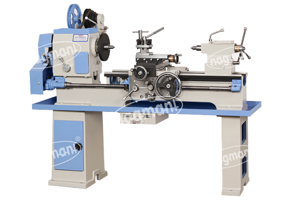 | Lathe Machine Lathe Machines are versatile machine tools used for accurately turning, facing, threading, boring, drilling, taper turning, and other machining... View product → |
Frequently asked questions
How do you calculate a lathe’s real turning envelope?
Measure the workpiece diameter and length in its actual setup, then add chuck or faceplate projection, tailstock contact, steady-rest position, tool overhang and chip-clearance space. Include chuck jaws and fixtures because they can exceed the finished part’s diameter.
Why should spindle, workholding and tooling capacity be selected together?
The spindle bore must pass the largest bar, while the chuck, jaws, faceplate, tailstock and tool system must safely hold and reach the work. Compare these capacities as one system instead of selecting a lathe by swing alone.
How do you choose between manual, CNC and other lathe types?
Base the choice on work mix: manual lathes suit varied one-off work and operator-led adjustments, while CNC lathes suit repeatable production, programmed toolpaths and consistent cycle times. Consider turning diameter, part length, batch size, complexity and automation needs.
What must you verify before accepting a lathe machine?
Confirm thread standards and pitches, spindle speed and torque, feed ranges, coolant arrangements, electrical and foundation requirements, chip handling, automation interfaces and documented acceptance tests for accuracy and performance.