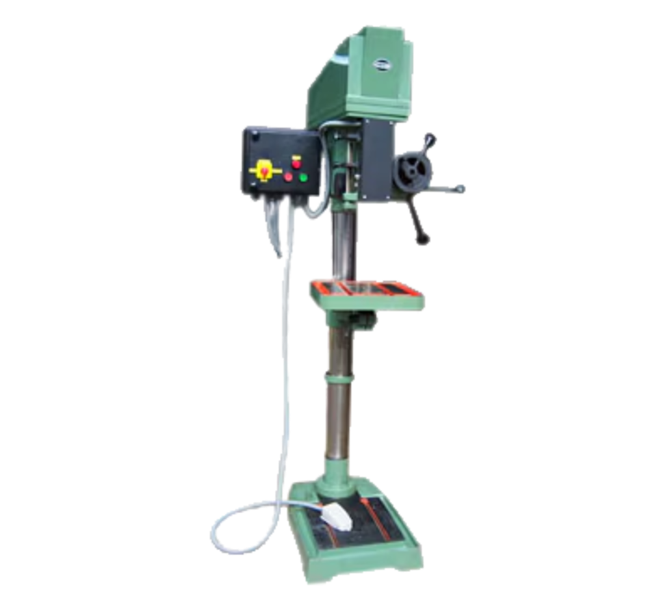
The finished thread is only as accurate as the hole beneath it: a tap follows the drilled hole rather than correcting its location or perpendicularity. By the end, you will know how to sequence both operations, choose the drill and tap for the hole type, calculate depth and feed, and compare machine specifications without assuming that every tapping machine provides rigid tapping.
Key takeaways
- Keep the workpiece clamped to one verified datum for both operations.
- Select tap-drill diameter and depth from the tap specification and blind-hole allowance.
- Use rigid tapping for synchronised spindle and feed control.
- Clear chips, apply suitable coolant, and avoid excessive tapping speed.
Keep the drilled hole and thread on the same datum
Lock the workpiece to a verified datum and complete drilling and tapping in one setup. Re-clamping between operations introduces hole-location shift, angular error, and datum error; keeping the part fixed provides datum error reduction and preserves the spindle-to-hole relationship. This does not correct poor fixturing, spindle runout, tool-holder runout, or movement during cutting.
Use this sequence for one hole:
- Establish the hole location from the drawing datum, then clamp the workpiece so the locating faces cannot lift or slide.
- Use spot drilling to create a short, concentric starting seat. A spot drill also helps prevent the twist drill from walking across the surface.
- Drill the tapping diameter to the required depth without moving the table, workpiece, or coordinate system. Hole location and perpendicularity are set here, not by the tap.
- Deburr the entrance or add the specified chamfer. A sharp burr can deflect the tap and damage the first thread.
- Start the tap in the same spindle position, using a rigid tapping cycle, tapping attachment, or controlled reversing spindle suited to the machine.
A tap follows the existing hole; it cannot relocate a hole that was drilled off datum. Check spindle and holder runout, clamp rigidity, and tool alignment before blaming the tapping operation for a misaligned thread. The combined setup saves handling time while keeping both operations referenced to the same coordinate system.
Choose the tap-drill diameter and total hole depth
Start with the tap-drill diameter from the tap maker’s chart for the exact size, pitch, material, and tap type. For a metric thread cut with a conventional cutting tap, the quick estimate is major diameter minus pitch: an M10 × 1.5 thread starts near 8.5 mm.
Treat that figure as a starting point, not a universal rule; thread percentage, hole tolerance, tap geometry, and material affect torque.
| Thread type | Diameter selection | Depth rule |
|---|---|---|
| Metric thread | Use the chart; major diameter minus pitch is a rough estimate for cutting taps | Add allowances below the usable thread |
| Unified thread | Use the chart for the specified UNC or UNF size; the estimate uses major diameter minus 1 divided by threads per inch | Confirm the tap’s required engagement length |
| Pipe thread tapping | Use the standard’s specified taper-tap drill, not the nominal pipe-size label | Include the required tapered engagement and bottom clearance |
For a roll-form tap, choose the smaller forming drill specified for that tap. A cutting-tap drill will not give the correct result because roll forming displaces material instead of removing it.
For a blind hole, make the drilled depth greater than the required usable thread depth. Allow room for:
- The drill-point angle
- The tap’s chamfered lead
- Chip space below the finished thread
- Clearance before the tap bottoms during reversal
Measure total hole depth from the surface, and program the tapping depth separately from usable thread depth. A hole only as deep as the required thread can leave incomplete bottom threads or break the tap.
Match the tapping method to the machine and hole type
Use a rigid tapping cycle when the machine has an encoder-synchronised spindle, controlled Z-axis feed, and programmed reversal. It maintains the tap’s pitch through acceleration and reversal, making it the best choice for repeatable production threads.
| Option | What it means | When it applies |
|---|---|---|
| Rigid tapping cycle | Spindle rotation and Z-axis feed stay synchronised | Production work, close pitch accuracy, and machines with true spindle-position feedback |
| Tapping attachment | A floating or compensating holder absorbs limited feed mismatch | Machines without rigid tapping, especially for moderate quantities and less demanding pitch control |
| Manual spindle reversal | You feed the tap in, stop at depth, and reverse the spindle under operator or basic-control command | Occasional work, slow tapping, and machines lacking both rigid tapping and a compensating holder |
Match the tap to chip flow as well as the machine. Use a spiral-point tap’s forward chip action for a through-hole; chips exit ahead of the tap instead of collecting in the flutes. Use a spiral-flute tap for a blind hole because it pulls chips back toward the entrance.
A blind hole needs extra depth beyond the usable thread length for the drill point, tap chamfer, chip space, and reversal clearance. Stop at nominal thread depth and the tap can bottom before reversing, leaving incomplete threads or breaking. A through-hole tap in that cavity can pack chips at the bottom.
Control speed, chips, coolant, and feed to prevent tap breakage
After drilling, set the tapping speed independently from the drill cycle. Choose tapping speed from tap material and coating, workpiece ductility, thread pitch, lubrication, and the machine’s reversal capability. Excessive speed raises torque and heat; insufficient lubrication can weld material to the cutting edges.
| Control | Setting or check | Damage prevented |
|---|---|---|
| Tapping speed | Use the tap manufacturer’s value for the material and tap type | Overload, heat, and edge chipping |
| Thread-pitch feed | In rigid tapping, feed equals rpm × pitch; an M10 × 1.5 tap at 500 rpm needs 750 mm/min | Pitch error, flank damage, and axial thrust |
| Chip evacuation | Use a spiral-point tap for through-holes and a spiral-flute tap for blind holes; clear chips before they pack | Jamming and tap seizure |
| Cutting fluid | Apply a fluid suited to the workpiece and tap; regulate through-tool pressure so it carries chips without foaming | Poor lubrication and unstable chip control |
| Spindle runout | Check the spindle, holder, and tap alignment before cutting | Uneven loading and premature breakage |
Keep drilling speed and feed tied to drill diameter, material, point geometry, and hole depth; do not copy those settings into the tapping cycle. Through-tool coolant can improve chip evacuation in drilling and deep-hole tapping, but excessive pressure or the wrong fluid can disrupt chip shape.
A tap follows the drilled hole rather than correcting it. If spindle runout or workholding movement exists, the tap reproduces that error in the thread and adds torque from misalignment. Stop immediately when torque rises, chips stop clearing, or the tap fails to reverse cleanly.
Compare the specifications that determine real tapping performance
A 40 mm maximum drilling diameter does not prove that a machine can tap large holes in production. Check tapping torque capacity, spindle reversal behaviour, and the control’s ability to match rotation with axial feed; motor horsepower alone is not enough.
| Specification | What to compare | What it reveals |
|---|---|---|
| Maximum drilling diameter | Rated diameter in your material, not only mild steel | Drilling capacity; it does not establish tapping torque |
| Tapping range | Tap sizes, thread pitches, and material limits | Whether the machine suits your actual taps, including coarse-pitch M10 or larger taps |
| Spindle-speed range | Lowest controllable speed and stable reversal | Whether you can tap ductile materials without exceeding tap speed |
| Quill travel and throat depth | Usable vertical travel and distance from spindle to column | Whether the tap reaches the hole while the workpiece clears the column |
| MT-2 or MT-3 spindle taper | Taper size, arbor fit, and tool retention | MT-3 generally supports larger tooling and higher loads than MT-2 |
| Machine rigidity | Column, quill lock, table support, and backlash | Whether cutting torque causes chatter, pitch error, or tap breakage |
For rigid tapping, verify a spindle encoder and synchronised Z-axis feed. An M10 × 1.5 tap at 500 rpm needs 750 mm/min feed; poor acceleration or reversal control can damage flanks. A floating holder forgives limited mismatch but cannot provide the same pitch accuracy.
When comparing machines from Valaba Machine Tools, request a torque-versus-speed curve and a demonstration using your largest tap and material.
Related products
 | DRILL MACHINE A flourishing enterprise in this domain, engaged in presenting a wide range of Drilling Cum Tapping Machine. View product → |
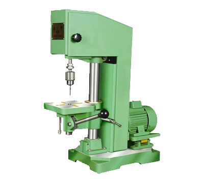 | DRILL MACHINE Our organization is widely appreciated in offering Drill Tapping Machine to our clients. Offered range is highly useful in different applications. View product → |
Frequently asked questions
Why should drilling and tapping use the same datum?
Keeping the workpiece fixed between operations preserves the spindle-to-hole relationship and reduces hole-location, angular, and datum errors. It does not compensate for poor fixturing or runout.
How do you choose tap-drill diameter and total hole depth?
Choose the tap-drill diameter from the thread size, pitch, material, and required percentage of thread. For blind holes, drill deeper than the finished thread to provide space for chips and the tap point.
Which tapping method suits a drilling cum tapping machine?
Use rigid tapping when the machine synchronises spindle rotation with feed. Use a floating or tension-compression tapping holder when the machine cannot maintain precise synchronisation.
How can you prevent tap breakage?
Match speed and feed to the tap and workpiece, control chip evacuation, apply compatible coolant, keep the tap aligned, and stop when cutting resistance rises.
Which machine specifications indicate real tapping performance?
Compare tapping capacity, spindle speed range, spindle torque, feed control, spindle-to-feed synchronisation, quill or stroke travel, chuck or holder type, and rigidity.