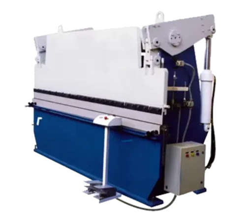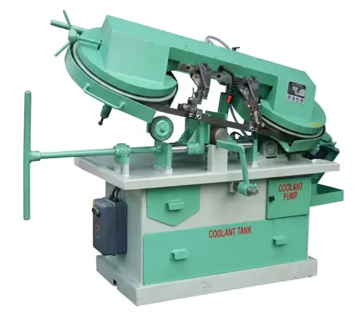
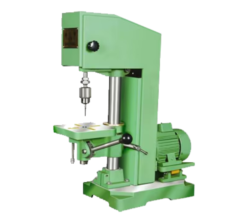
Productivity losses in drilling and tapping rarely come from spindle speed alone. They come from repeated setups, poor hole preparation, unsuitable tap geometry, unsynchronised feeds, avoidable tool changes, and inspection failures. By the end, you will be able to map the operation, calculate its real cycle time, select suitable cutting conditions, and decide whether a drill-tapping machine fits the work.
Key takeaways
- Prepare fixtures, tools, offsets, coolant, and gauges before production.
- Measure the complete drilling and tapping cycle, including loading and inspection.
- Set hole size, speed, feed, and tapping depth from the job requirements.
- Use correct alignment, lubrication, and chip control to prevent tap breakage.
Build a Repeatable Drilling and Tapping Workflow
Treat the drill tapping machine workflow as a fixed sequence, not a series of operator decisions. Prepare the fixture, datum, drill, tap, offsets, coolant, and inspection gauges before production; this cuts setup time and prevents mid-run searches for tools.
- Load and clamp the part against a repeatable stop. Confirm the drawing datum, hole locations, hole depth, tap type, and manufacturer’s pre-hole size before starting.
- Run the first hole slowly enough to verify position and depth, then drill every hole in the planned toolpath. Optimise rapid approach and retract distances, but keep the drill clear of clamps and the workpiece.
- Start the tapping cycle only after the drilled hole passes the diameter and alignment check. With rigid tapping, use the control’s synchronized spindle reversal and recovery procedure; never substitute an arbitrary retract feed.
- Inspect the first completed thread with the specified plug gauge, then check hole position, thread depth, and chips at a defined interval. Stop the batch when a gauge fails instead of compensating blindly.
- Retract the spindle, stop rotation, and remove the finished part while the next blank is within reach. Clear chips with a brush or approved air method, not your fingers.
Preset tools and group parts by common drill or tap sizes to reduce tool change time. The largest gains in the drilling and tapping cycle usually come from fewer tool changes, shorter approaches, and smoother part handling rather than higher rpm.
Calculate Productivity From the Complete Cycle
Compare the complete cycle per finished part, not the cutting time of either machine. Start the clock when the operator begins loading and stop it after inspection and part removal. Record holes per part, tapping depth, tool changes, setup allocation, and operator handling time for both methods.
| Method | Cycle-time components to record | Productivity result |
|---|---|---|
| Combined drill-tapping machine | Drilling time + tapping time + tool-change time + approach and retract time + loading, inspection, and removal | Parts per hour = 3,600 ÷ complete cycle seconds |
| Separate machines | Drilling cycle + transfer time + tapping cycle + second loading and unloading + queue or batch-transfer time | Parts per hour = 3,600 ÷ total elapsed seconds per finished part |
For each hole, calculate drilling time from cutting length ÷ feed rate. For rigid tapping, use feed rate calculation: feed in mm/min = spindle speed in rev/min × pitch in mm/rev. Include the full tapping depth and the synchronized reversal and withdrawal period; a faster spindle does not eliminate that time.
Example: a combined cycle of 72 seconds produces 50 parts in an hour before utilisation losses. Separate machines taking 34 seconds to drill, 29 seconds to tap, and 18 seconds for transfer and handling require 81 seconds, producing about 44 parts per hour.
Measure at the same batch size and include setup time divided across the batch. Validate rigid-tapping recovery before timing production; feed-hold or unsynchronized retract can damage the tap and invalidate the comparison.
Set Hole Size, Speed, Feed, and Tapping Depth Correctly
Start with the hole, not the tap: choose the finished thread diameter and pitch, then size the predrilled hole from the tool manufacturer’s table. For metric tap sizes, the familiar major diameter minus pitch estimate applies only to certain cutting taps and thread percentages.
Inch taps use their own Unified or other standard tables; do not convert by guess. Coarse and fine pitches, tolerance class, and thread percentage change the required hole.
- Select speed from material and drill diameter. Calculate spindle speed from cutting speed: n = 1000Vc ÷ (πD), then reduce it for hard alloys, poor rigidity, or difficult chip control.
- Set tapping feed from pitch and spindle speed: feed in mm/min = spindle speed in rev/min × pitch in mm/rev. Rigid tapping must keep those values synchronized; mismatch loads the tap in compression or tension.
- Use the correct tap style. A cutting tap removes chips; a form tap displaces material and needs a larger hole. Using a cutting-tap drill size for a form tap raises torque and can distort the thread, especially in hard or non-ductile material.
- Add depth for blind holes. Drill beyond the finished thread length to accommodate the tap chamfer and chips below the thread; otherwise the tap can bottom out before reaching depth.
Check the drilled diameter, runout, straightness, and bell-mouth before tapping. An undersized hole raises torque, while an oversized hole reduces thread engagement and strength, so changing speed will not repair a faulty drilling step.
Match the Machine and Tapping Method to the Job
Choose rigid tapping for CNC production when the control synchronizes spindle rotation, reversal, and axial feed. Set feed in mm/min to spindle speed in rev/min multiplied by tap pitch in mm/rev; a mismatch loads the tap in compression or tension.
Validate feed-hold and recovery before production, because an unsynchronized retract can damage both tap and thread.
| Option | What it means | When it applies |
|---|---|---|
| Rigid tapping | Spindle and Z-axis remain synchronized | Repeated CNC work with controlled pitch, depth, and thread quality |
| Tapping chuck | Holder provides limited axial float to absorb mismatch | Conventional drilling machines or small setup variations; it cannot correct poor feed settings |
| Tapping attachment | A clutching or reversing head controls tapping torque and direction | Drill presses that lack rigid tapping, especially for repeated holes |
| Reversing spindle | The spindle changes direction at the programmed tapping depth | Machines with reliable forward/reverse control; pair it with suitable feed control or a compensating holder |
Do not select by maximum rpm alone. Low-speed torque, reversal time, synchronization, tap surface-speed limits, and coolant compatibility determine actual output. Ask Valaba Machine Tools to document those points before comparing a drill-tapping machine with another model.
Choose another machine when the job needs milling, interpolation, heavy material removal, or very deep blind-hole tapping beyond the machine’s torque and chip-control capability. A dedicated tapping machine suits high-volume, single-purpose work better; a machining centre suits multiple features and positional accuracy.
A basic drill-tapping machine is the wrong choice if it cannot prove repeatable depth recovery and thread inspection results.
Related products
 | DRILL MACHINE Our organization is widely appreciated in offering Drill Tapping Machine to our clients. Offered range is highly useful in different applications. View product → |
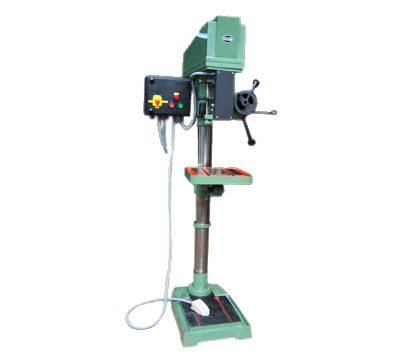 | DRILL MACHINE A flourishing enterprise in this domain, engaged in presenting a wide range of Drilling Cum Tapping Machine. View product → |
Prevent Tap Breakage and Verify Thread Quality
Check the drilled hole before blaming the tap. Measure diameter with a plug gauge or pin gauge, and check runout, straightness, bell-mouthing, and a damaged drill point. An oversized hole reduces thread engagement; an undersized hole raises torque and can break the tap.
Use this inspection sequence:
- Confirm the drill diameter against the manufacturer’s table. A form tap needs a larger hole than a cutting tap because it displaces material instead of cutting chips.
- For blind-hole tapping, drill beyond the finished thread length so the chamfer and chips have clearance. A tap that bottoms out will fail even at the correct depth.
- Match the tap geometry to chip travel. Use a spiral-flute tap to pull chips toward the entry in a blind hole; use a spiral-point tap to push chips forward during through-hole tapping.
- Apply a compatible tapping lubricant and clear packed chips between parts. High-pressure coolant can worsen chip control.
- Check spindle-feed synchronisation in rigid tapping: feed in mm/min = rpm × pitch in mm/rev. A mismatch loads the tap in compression or tension and causes cross-threading or damaged threads.
- Inspect the finished thread with the correct GO and NO-GO plug gauges. Reject a part if the GO gauge will not pass fully or the NO-GO gauge enters beyond the specified limit.
| Tap choice | Chip direction or material action | Main process check |
|---|---|---|
| Spiral-flute tap | Pulls chips upward | Blind-hole clearance |
| Spiral-point tap | Pushes chips ahead | Through-hole chip exit |
| Form tap | Displaces material | Larger manufacturer-specified hole size |
Frequently asked questions
How do you build a repeatable drilling and tapping workflow?
Prepare the fixture, datum, drill, tap, offsets, coolant, and inspection gauges before production, then follow the same sequence for every workpiece.
How should you calculate productivity for a drill tapping machine?
Measure the complete cycle: loading, clamping, drilling, tapping, retracting, unloading, inspection, and any tool changes or interruptions.
What parameters must you set before drilling and tapping?
Confirm the hole size, spindle speed, feed rate, tapping depth, coolant or lubricant, and the required thread specification before running the job.
How can you prevent tap breakage and verify thread quality?
Align the workpiece and tap, control chip formation and lubrication, avoid excessive depth, and check finished threads with the specified plug gauge or mating part.