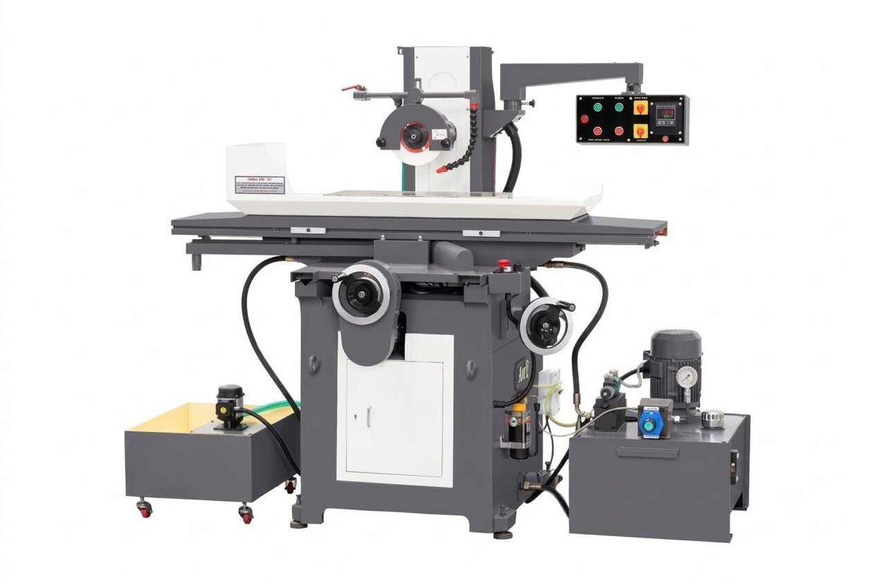
A hydraulic surface grinder improves finishing by controlling the table’s reciprocating motion while the wheel removes small, measured amounts of material from a supported workpiece. To judge whether it will deliver the required result, you need to understand the grinding sequence, distinguish flat-surface work from other processes, and compare specifications that affect accuracy, heat, vibration, and repeatability.
Key takeaways
- Control table speed, cross feed, and down feed to manage stock removal.
- Check machine geometry, chuck condition, dressing, and temperature for flatness.
- Choose wheel grade and dressing conditions for the workpiece material.
- Use spark-out passes and coolant control to reduce taper, burn, and chatter.
How the hydraulic surface grinder controls the cut
A flat finish comes from coordinated motion, not hydraulic power alone. In hydraulic surface grinder operation, the table travels the workpiece back and forth beneath a rotating wheel at a controlled speed. This repeatable path supports consistent removal, but flatness and parallelism still depend on machine geometry, wheel dressing, chuck condition, workholding, and temperature stability.
- The hydraulic table drive moves the table through each longitudinal stroke and reverses it smoothly. Contaminated oil, air, worn seals, or a sticking valve can cause jerky motion, speed variation, or end-of-stroke creep.
- The spindle rotates the grinding wheel at the required peripheral speed. Correct mounting and balancing prevent periodic chatter marks, uneven finish, and excess bearing vibration.
- The magnetic chuck holds the workpiece against the table. Burrs, scale, coolant film, or a bowed underside create air gaps and reduce holding force.
- The cross-feed shifts the table or chuck sideways after successive strokes, spreading the wheel path across the surface.
- The vertical feed lowers the wheel toward the workpiece and sets the depth of cut.
Roughing uses larger downfeeds to remove stock; finishing reduces each pass to micrometre-scale movement. The cross-feed covers the full width, while spark-out passes let the wheel travel without further vertical feed, reducing spring-back marks. Direct coolant into the wheel–work contact zone to carry away heat.
What happens during a real grinding job
1. Start with workpiece cleaning and mounting. Remove chips, oil, rust, and burrs from the part, magnetic chuck, and supporting parallels. Seat the workpiece fully; a trapped chip can tilt it and produce a false flat surface. Confirm that the magnet holds securely before starting the table.
2. Check the wheel before contact. Mount the correct abrasive for the material, balance it, and verify the guard and flange. Dress the wheel to expose sharp grains and restore its profile. After mounting a different wheel or adapter, balance it again.
3. Set the wheel speed and feed from the wheel rating, material, rigidity, coolant flow, and stock allowance. Take a light trial pass, then reduce the downfeed as you move from roughing to finishing. Excessive infeed generates heat, loading, and burn.
4. Grind with coolant directed into the contact zone, allowing the reciprocating table and cross-feed to cover the required area. Stop programmed downfeed when the surface reaches size, then make spark-out passes. These passes remove elastic deflection and small high spots, but they cannot fix poor alignment or uneven support.
5. Stop the wheel and let the workpiece reach a stable measuring temperature. Wipe it clean, then check thickness, flatness, parallelism, and surface finish with the specified instruments at several locations.
6. Switch off the magnet before lifting the part, and keep your hands clear of the wheel and table. Break sharp edges, inspect for burn or chatter marks, and clean the chuck before the next job.
Which parts and features suit surface grinding
Surface grinding suits plates, dies, fixtures, guideways and hardened flat parts that need a controlled planar face, close thickness, or a fine, uniform finish. The process produces a flat surface and can establish parallelism between faces, but a low Ra value alone does not prove flatness; taper, waviness, convexity or concavity can remain.
| Part | Useful result | Check before grinding |
|---|---|---|
| Plates | Flat faces and controlled thickness | Length, width, thickness and magnetic holding area |
| Dies | Accurate die faces, lands and backing surfaces | Work height, wheel clearance and hardened-material removal rate |
| Fixtures | Flat locating faces and repeatable reference surfaces | Weight, clamping access and whether magnetism affects the fixture |
| Guideways | Straight, flat sliding surfaces | Table travel, required parallelism and support along the full length |
| Hardened flat parts | Fine finishing after heat treatment | Wheel clearance, chuck capacity and risk of magnetic distortion |
Check five limits against the actual workpiece, not just the advertised table size:
- Maximum grinding length and width must cover the part plus the table’s usable stroke and cross-travel.
- Maximum height must include the workholding method, magnetic chuck, fixtures and wheel diameter.
- Maximum table load must include the workpiece, chuck and any auxiliary support.
- Vertical feed and spindle clearance must allow wheel approach, dressing allowance and the required final thickness.
- Chuck dimensions, magnetic force and support must suit thin or stress-relieved parts; excessive pull can flatten a flexible part during grinding and leave it concave or warped after release.
A machine’s reciprocating table provides repeatable motion, not guaranteed geometry. Spindle-to-table alignment, chuck condition and thermal stability determine the finished feature.
Which specifications reveal useful machine capability
Compare the machine’s stated capacity with the part you will actually hold, grind, and measure. A large table does not guarantee a flat result, and a high spindle motor power does not compensate for poor geometry, chuck condition, or thermal drift.
| Specification | What it reveals | What to verify |
|---|---|---|
| Table size and magnetic chuck size | Maximum support and usable clamping area | Chuck dimensions, rated workpiece weight, and clearance around the wheel |
| Longitudinal and cross travel | Whether the wheel can cover the complete surface | Travel after allowing for chuck, wheel diameter, overtravel, and workpiece length |
| Spindle speed, spindle motor power, and runout | Wheel speed, cutting reserve, and vibration risk | Rated speed for the wheel, measured runout, balancing method, and mounting taper |
| Hydraulic flow and pressure | Table speed control and resistance response | Flow and valve adjustment for reciprocation; pressure alone does not prove speed accuracy |
| Automation | Consistency between parts and operator workload | Automatic downfeed, cross-feed, spark-out, dressing, stroke limits, and cycle storage |
| Coolant delivery | Heat removal at the wheel–work contact | Nozzle position, filtration, tank capacity, and flow that continues during the cut |
| Accuracy data | Finished-part capability | Test methods and results for flatness, parallelism, surface texture, table straightness, and thermal drift |
Ask Valaba Machine Tools for a sample inspection report rather than accepting only catalogue dimensions. Require repeatability and accuracy as separate figures, with the measuring instrument, datum, temperature, and test length stated. A pressure gauge reading or minimum downfeed figure alone predicts very little.
Related products
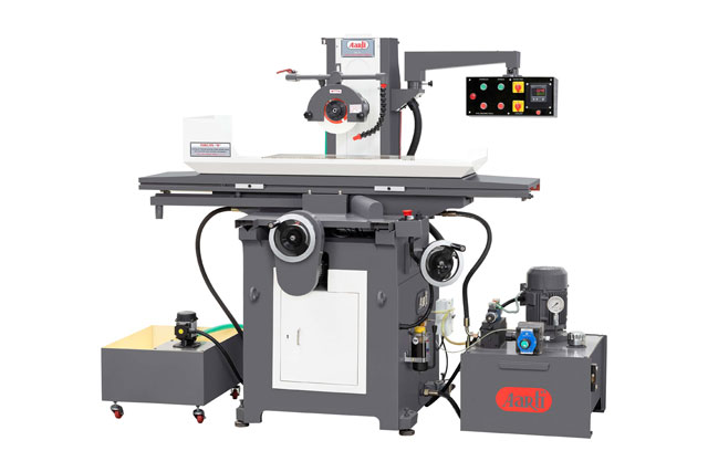 | SURFACE GRINDERS Hydraulic Surface Grinding Machines Hydraulic Surface Grinding Machines are precision grinding solutions designed for accurate and efficient surface finishing of metal components. View product → |
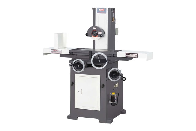 | SURFACE GRINDERS Manual Surface Grinding Machine The Manual Surface Grinding Machine is a precision grinding solution designed for accurate surface finishing and machining of metal components. View product → |
How wheel choice and process control prevent defects
1. Match the abrasive to the workpiece and stock-removal rate. Use aluminum-oxide wheels for most steels; choose silicon-carbide wheels for cast iron, nonferrous alloys, and selected carbide work. Set the grit size, wheel grade and bond for the finish and cut required: the wrong combination causes loading, glazing, burn, or frequent dressing.
2. Mount the wheel correctly, then balance it after mounting and whenever the wheel or adapter changes. Dress it with the correct depth and traverse so fresh abrasive cuts instead of rubbing. A dull wheel or closed dressing condition can create grinding burn and size growth even during a light finishing pass.
3. Aim filtered coolant directly into the wheel–work contact zone. A flood that misses this point will not remove heat, while interrupted flow can cause burn, cracking, or size drift.
Select filtration for the wheel, material, and finish target; a filter intended only to protect the pump can return abrasive swarf to the nozzle, scratching the surface and accelerating loading.
4. Clean the magnetic chuck and workpiece, seat the part fully, and support thin or flexible areas. Excessive magnetic force can distort a thin plate; releasing it can reveal taper or uneven removal. Check parallelism and use a suitable arrangement of parallels or stops when the magnetic field does not hold the part uniformly.
5. Rough with deeper downfeeds, then reduce each finishing pass to micrometre-scale movement suited to the machine, material, rigidity, and wheel condition. Use spark-out passes after the final feed to reduce taper and uneven removal, and inspect for periodic chatter marks and grinding burn before removing the part.
Frequently asked questions
How does a hydraulic surface grinder control the cut?
The hydraulic system drives reciprocating table travel, while cross feed, down feed, wheel dressing, and machine geometry control material removal and finish.
What happens during a real surface grinding job?
You secure and indicate the workpiece, dress the wheel, take controlled roughing passes, apply finishing passes, use spark-out, and inspect flatness and parallelism.
Which machine features support surface grinding?
A rigid table, stable hydraulic drive, accurate ways, a reliable magnetic chuck, controlled down feed, wheel guard, coolant system, and effective wheel dressing support consistent results.
Which specifications reveal useful machine capability?
Compare table size, maximum workpiece weight, longitudinal and cross travel, grinding wheel dimensions, spindle speed, down-feed resolution, hydraulic pressure, and stated flatness accuracy.
How do wheel choice and process control prevent defects?
Match abrasive type, grit, grade, and bond to the material; then control dressing, coolant flow, feed rates, and spark-out to prevent burn, chatter, loading, and taper.
Related product
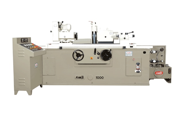 | CYLINDRICAL GRINDING Hydraulic Cylindrical Grinding Machine The Hydraulic Cylindrical Grinding Machine is a high-precision grinding solution designed for external, internal, and face grinding of cylindrical... View product → |